Electrical Corner

Periodical Tidbits

What are relays? Wiki Answers
Showing posts with label upgrade. Show all posts

Tuesday, February 5, 2013

Battery Cabling Upgrade - The BIG 3 (Jeep TJ)

Short Story First

I started looking into this after 10 yrs of owning and using my Jeep because of the general purpose battery I picked up Summer of 2012.  I made the mistake of getting a replacement battery quickly as the last one was not holding a charge and giving me trouble with starting the vehicle.  So after getting the new battery from from a local auto parts place (not blaming them by the way) all was back to normal.  Then I forgot about the reason you don't by just any battery for a vehicle you wheel/offroad - battery acid leaking from the top.  So after a few months I had trouble starting the vehicle again.  Long story short, the negative battery terminal corroded so much I could no longer keep the ground terminal connector on the battery.  I had to brush the terminal every day and carefully twist the connection in order to allow the Jeep to start.  Never mind the problems this could cause to the entire electrical system in the vehicle (i.e. main computer going bad).  So instead of jumping to buy a new battery, I decided to first change out the wiring and connectors for the starter and charging system, then buy a good battery shortly after (spill proof).

Upgrading the BIG 3

!!LOTS AND LOTS OF PICS BELOW

A few concepts you should know:
(1) I am NOT looking to install a high end audio system in the vehicle, but if I do, this will still apply;
(2) I did NOT change my stock alternator to a high output alternator - working just fine (should know, however, that if you plan on needing more power, more often, keep in mind the need for a high output Alt.  If you push it to the peak often it will die.  They have a normal operating range and a peak range.  Peak is meant for spike only and not continuous draw.)
(3) I AM looking to upgrade the stock wiring in case of potential changes in the future with the need for higher draw of the electrical system, but for now, starting the vehicle and the basic electrical system running like a champ is the primary focus (no more dimming/flickering lights, difficult starts, etc).

Definition

In a TJ, the engine start and main power distribution consists of:
1) Battery Positive to the starter positive
2) Battery Positive to the Fuse Box
3) Alternator Positive to the Fuse Box
4) Battery Negative to the Chassis
5) Battery Negative to the Engine Block

Cost

Overall this is not expensive.  If you went to the dealer for a replacement harness, you would be paying about the same thing or more and still only have the same stock kit, and that's if you install it yourself.  So why not upgrade?

Parts you will need:

The better quality parts you buy the better life expectancy and performance you will gain.  Make sure all the metal parts are copper as it is the best/most common electrical conductor.  Some parts may be tin dipped for corrosion protection, which is common for the lugs.  This is a fine quality to have.  The copper should be stated as oxygen free copper (OFC).
  • Power wire/cable (went w/ 4-gauge due to cost, flexibility, and its ability to supply the power necessary for this application.  When doing installs for accessories such as lights, amp, winch, etc you'll have different needs, but will not impact this upgrade.  Those wires are separate.)
  • Lugs 
    • @8 - straight 4-gauge 3/8" hole
    • @2 - 90 degree 4-gauge 1/4" hole
  • Heat shrink
  • Terminal connectors @2 (preferrably polarized)
  • Terminal protectors (optional)
  • Electrical solder (silver rosin is fine - again a great conductor of electricity)
  • Gas torch
  • Lug hammer (clamps lugs onto cable)
  • C-clamp or hammer for the lug hammer tool (I prefer a c-clamp)
  • Quality cable cutters (like a hot knife thru butter)


Some of my order details (priced around and these were the best parts for the price):
Cloud Electric
LU-1823HD: Lug straight heavy duty 4-gauge 3/8' hole [copper and tin dipped] $0.86 ea.

REMY Battery
4266-001: Brute hammer tool [didn't use a hammer but a c-clamp to control the squeeze on the lug; simple and less chance for error and things getting broken] < $14
5952-050DL: Lug 90 degree 4-gauge 1/4" hole

KnuKonceptz:
KFX4BK Kolossus Fleks Kable 4 Gauge Power/Ground wire (Black) [per foot; I ordered 10ft]
KFX4R Kolossus Fleks Kable 4 Gauge Power/Ground wire (Red) [per foot; I ordered 10ft]

Lowes
Cable cutter that would cut 4 ga cable (not easy to find in most local stores it turned out) ~$26
Electrical tape (just in case) < $1

Harbor Freight
Zip-ties ~$2

Racer Parts Wholesale
FAS-405-911: Fastronix Military Spec Battery Connectors - Negative Terminal  $5
FAS-405-910: Fastronix Military Spec Battery Connectors - Positive Terminal  $5

Car Quest
TA21: Heat Shrink - Heavy Wall Polyolefin Heat Shrink W/ Sealant - 6" - 1 Red - 1 Black <$10

New Red 4ga Cabling
New Black 4ga Cabling


The Results


Steps to Create the Cables

Before cutting the cable to size, be sure to take measurements.  There are many ways of doing this.  I prefer to keep this simple as it doesn't need to be exact, need some slack, but not too much.  I put one of the new cable at a stock connector position in the engine bay and unrolled the new cabling to stretch the length of the stock cable to a connector at the other end.  Using the cable cutters, clipped the new cabling.  I did this one at a time 'til all were measured and cut.  Be sure to remember which one is which for when you install and also for when you create the fuse box connections as they are the smaller lugs.


1 - Cut wire a box cutter/razor blade a little over 1/2" of the insulation off the cable end

2 - Pull the insulation off to expose the copper wiring and carefully with clean fingers, pull'push the strands of wire together so their aren't any strays.

3 - Carefully insert the exposed copper strands into a lug


4 - Using the hammer tool, crimp the lug so that it squeezes the copper strands
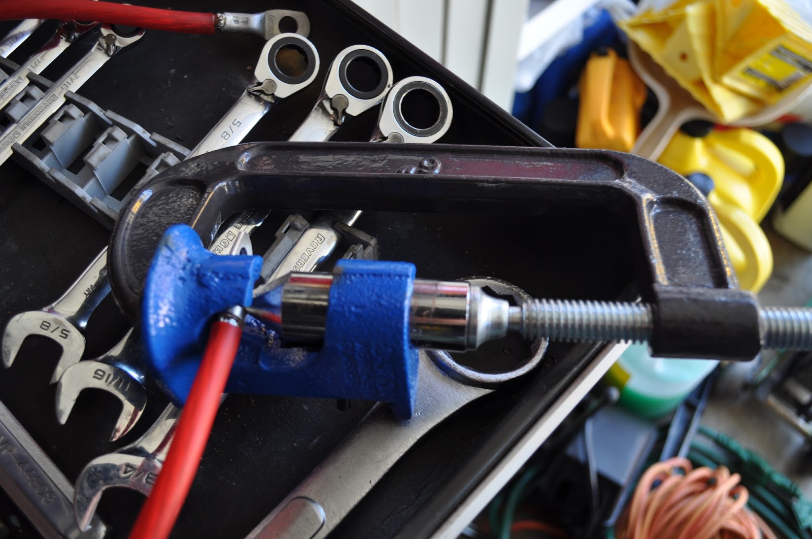


5 - Solder the connection making sure not to burn the cable insulation.  This will make the connection incredibly solid.


6 - Protect the connection by sealing it with heat shrink.  Place the shrink over the connection area and lightly apply heat from the torch to the shrink by going back and forth over the heat shrink with the torch flame.  Eventually you will see it shrink and possibly some of the sealant come out.  When you see no more gap, stop.  Should take more than about 30 seconds to complete.  Be careful not to set it all on fire!  You left the flame on the shrink to long - wave the flame over the shrink, back and forth to prevent this.


7 - Repeat for all cable ends, then your done!


Before and After Shots


Stock wiring pulled
* Didn't use the box cutter to remove; just put in the pic to give context


Before - Alternator


After - Alternator  


Before - Fuze Box (all positive connections) 


After - Fuse Box (All positive connections) 


Before - Starter 


After- Starter
* First pic shows both the stock and the new cable & lug side-by-side


Before - Overview Stock setup


After - Upgraded New Setup


Negative (Ground) to Chassis off Battery


While I was in there, I pulled the battery (new one going in soon) and cleaned up the pan and its mounting brackets

Before
*10 Yrs of abuse and it is still in really good shape - nothing a little loving care can't fix

After


Tuesday, July 17, 2012

TJ Speaker Upgrade from Stock Speakers

Intro

I didn't see a total write-up for doing this, but did find some details here and there. I pulled together everything I learned and know for this install into one place for those thinking about doing an upgrading to their speakers.

The following will show how I replaced my stock speakers for my 2003 TJ to Polk Audio DB651s Slim-Mount 6.5” (soundbar) and Polk Audio DB461P 4x6” (dash). At the time I purchase them, Amazon was having a huge sale on all car audio, 50% off on average. Also, I did not bother to purchase the conversion cables as I wired the connectors using standard female crimp-on connectors. I’ll explain how to do this.


The Polk speakers I selected are marine rated, for those days the Jeep get wet inside :)

Also, the Polk 4x6 dash speakers are not oval speakers but true round speakers on squared frames. I read some people think oval speakers have poorer quality than round speakers. Perhaps, not sure, but wanted to point this out.

Note I did not replace the stock wiring, head unit, sub, or install an amp at this time. So nothing here will help you with that. [Although I did replace my sub last year with a Pyramid 6.5-Inch High Power White Injected P.P. Cone Woofer…plug’n’play for the TJ and sounds so much better!]
Pyramid WX65X 6.5 in. High Power White Injected P.P. Cone Woofer

Speaker Power

DB461P 
RMS rating: 50 watts / speaker
Peak rating: 150 watts

DB651s 

RMS rating: 55 watts  / speaker
Peak rating: 165 watts

RMS = continuous power

Tools & Parts you will need

  • A drill and 3/32” drill bit 
  • 4 Female ¼” crimp-on connectors for 22-16 guage wiring
  • 4 Female 3/16” crimp-on connectors for 22-16 guage wiring
  • (optional) substitute two 3/16” and two ¼” female crimp-on connectors 22-16 guage (above) for 14 guage crimp-on connectors if you want to extend the dash wiring like I did (see below section for details)
  • (optional) 14 gauge crimp-on butt connectors if you extend the dash wiring like I did
  • Depending on your stock speakers you may need to fabricate brackets for the new speakers. I decided not to and kept it clean and simple (I go into why below) and picked up brackets made for my TJ to install 4x6 speakers (see below pic for part details)
  • Crimpers, philips and flat head screw drivers, wire stripper, and wire cutters
  • There is also some upgraded 14guage wiring for the dash speakers in the pic below (optional if you upgrade the dash wiring like I did). I just could deal with buying cheap wiring like what is already in the TJ with the better wire being so cheap.
  • Poly-Fil to fill the voids behind the speakers; one bag did the entire vehicle with a little to spare (see pic below;less than $9)

Some of the tools & parts needed as stated above

Butt Connectors [optional per above description]

New brackets for dash speakers - got these from Crutchfield very cheap over-night free shipping along with the new 14 gauge wiring. They are oval, but the Polk speakers I bought fit perfectly.


Female crimp-on connectors for stock wiring (22-16 gauge) 


Female crimp-on connectors for extended, upgraded, wiring (16-14 gauge)


Dash Speakers

Soundbar Speakers


Poly-Fil


Positive & Negative Speaker Wiring

Drive’s Dash
Green - ( + ) Positive
Red/brown - ( - ) Negative

Passenger’s Dash
Blue - ( - ) Negative
Purple - ( + ) Positive

Soundbar:
Positive Wire (+): Brown/Yellow
Negative Wire (-): Brown/Blue

Note
Always keep the screws you remove as you will need most of them to put things back together.

Dash Speaker Install

Remove the dash speaker cover.  Two screws hold the cover on. 

There are two clips to help hold the dash cover in place.  Pull the cover off by hand.  Sometimes the clips come off the cover and stay in the dash.  Just pull them out from the dash and slide back onto the back side of the cover.


Remove the stock speaker by first removing the four screws holding it in place (2-top; 2-bottom). Then Remove the wire by disconnecting the stock wire connector.


Here is the problem with the dash wiring.  It barely reaches out from the dash.  I wanted more room to work with so I extended the wire a foot on both sides using the 14 gauge wire.
(passenger side stock connector)


New 14 gauge wiring I used to extend the dash stock wiring

How to Extend the Dash Speaker Wire
  1. Remove the stock speaker connector by cutting the stock wire near the back of the stock speaker connector.
  2. To make it easier to work with the wire I pulled the stock speaker wire under the dash to gain more room to fit my hands.
    (driver’s side red and green speaker wire shown here)
  3. Strip the Negative wire insulation ½” to expose the copper wiring. 
  4. Twist the copper wiring in order to make a clean connection into the new crimp-on connector. 
  5. Insert the exposed copper wire into a butt connector (for extending the wire) and crimp it 
  6. Strip the new 14 gauge wire plastic covering 1” making sure not to cut the wiring underneath 
  7. Strip the Negative wire insulation ½” (I chose the blue wire to make it easier to know later if I ever take the speakers out again) 
  8. Twist the wiring in order to make a clean connection into the new connector 
  9. Insert the exposed wire into the other end of the butt connector already connected to the stock speaker Negative wire and crimp 
  10. Repeat steps 1 thru 8 for the Positive wire. 
  11. Pull the wiring back up through the dash where the speaker will be installed
Now we’ll walk through the install for the female connectors that will connect to the speakers
  1. Cut the new 14 gauge wire so that you have about 9 to 12” of length stretching out from the dash (my preference, as you can cut longer or shorter as you need) 
  2. At the end of the 14 gauge wire strip the Negative wire insulation ½” to expose the wiring 
  3. Twist the wiring in order to make a clean connection into the new female crimp-on connector 
  4. Insert the exposed wire into a 3/16” female crimp-on connector for the 14 gauge wire and crimp 
  5. Repeat for the Positive wire but use a ¼” female crimp-on connector for the 14 gauge wire.
Before doing anything else I would test the connection, making sure the female connectors are hot.  To do this, turn the Jeep on for power to the radio, turn the radio on, volume up a bit and connect a new dash speaker to the wiring: positive to positive (1/4” connection); negative to negative (3/16” connection).  Now you know that the new connections are correct and the wires are hot to the speakers.  Disconnect the new dash speaker.

Use electric tape to wrap up any exposed wires but do not cover the female connectors.

Here is the dash wiring after being extended – so much easier to work with now.

So easy my son can do it!

Now to Install the Speakers into the Dash

Old and new speakers side-by-side.  You can see they are short as the brackets make the stock speakers longer.  Some are able to cut as they have different speakers, the stock speakers in my TJ have a plastic casing including the brackets for the screws…you can see in the pics below and above.

Mount the new brackets to the new speakers

Connect the wiring to the back of the speaker – positive to positive (1/4” connection); negative to negative (3/16” connection).  You may need to squeeze the ¼’connector because it may slightly slip off the speaker connection I found.  If so, w/o the wire connected to the speaker, use the crimp tool to compress the female connector a VERY tiny bit.  When you slide it on, you should feel it holding in place w/o slipping off.
Now, put the speaker into position to be screwed back into the dash and install the dash cover.

UPDATE 23Jul2012: Added Poly-fil


Repeat the entire process for the other side.

The dash speaker upgrade is complete!


Soundbar Speaker Install

Soundbar before (stock '03 TJ)

Four Philips screws hold the cover on.  After taking the cover off glue will be holding the speaker to the soundbar.  Just pull it off by hand or by using a flat head screw driver to gently pry around the speaker from the soundbar.

Disconnect the stock speaker from the stock connector.


Change the stock connector to a standard female speaker connector

Same procedure used as above; however, the extension of this speaker wire was not necessary in my TJ as the wire was already long enough for me.  So you may not want to extend it.  Your call.


Installing the New Speaker


When you take the new soundbar speakers out of the box it will have a foam seal for between the speaker and the mount point.  Remove it from the new speaker, temporarily, place it somewhere safe.  This will allow you to more easily position the speaker to find the correct position to mount the new speaker to the soundbar.  The new speaker is larger than the stock hole, but no need to do any cutting. 

For the following it was important to me to position the speaker correctly to meet the following:
  • Not to reuse the stock holes as they did not line up correctly 
  • Positioned the speaker so not to fastened it unbalanced 
  • Pay special attention to the four holes that line up for the speaker cover and the other three that don’t
You should note the screws that come with the new Polk speakers for the soundbar are not long enough to screw through the cover, speaker, and into the soundbar and hold it all in place.  I reused the four stock screws to fasten the new speakers to the sound bar and used the nice shiny screws to hold the speaker cover on (barely reaches into the soundbar, but do enough of a job - perhaps I'll change them to long, wider screws, but they have held up for the time being.)


Poly-Fil

Before installing the speaker fill the void in the soundbar hole with Poly-Fil to help deaden the vibrations.  It has made a difference as I did this after installing and used the speakers for a few weeks.


Steps:

  1. Position the new speaker in the hole centering it best you can and using a drill with a 3/23” drill bit, drill the first hole only.  In the blue circles (see above pic) there are two holes in the speaker; be sure to focus on the holes not lined up with the speaker cover. The red circle are the screw holes that line up with the speaker and the cover.
  2. Using this single hole drilled, find one of the stock screws and hand screw the speaker to the soundbar. IMPORTANT not to use a drill as you will over tightened and potentially strip the hole. It will be a bit tight, which is what you want. Do not tighten all the way, just enough to hold the speaker up while you position the speaker again to drill a hole on the other side of the new speaker into the sound bar making sure to balance the position of the speaker onto the soundbar
  3. Screw the second drilled hole using a stock screw and finish drilling the third hole. Do not screw it in yet.
  4. Now, unscrew the two you just put in
  5. Connect the speaker and test that sound comes out.
  6. If the speaker connection is good proceed; otherwise figure out what is wrong
  7. Disconnect the speaker from the wiring
  8. Remember the foam seal? Get it and position it correctly onto the back of the speaker (see following pic)
  9. Connect the speaker wiring
  10. Position the new speaker to the newly drilled holes in the soundbar and hand screw using the stock screws. Do not over torque. Just enough on each screw to stop it from moving.
  11. Once all three are tightened where the speaker doesn’t move drill remaining holes for the speaker cover
  12. Position the speaker cover over the speaker and using the Polk provided screws, hand fasten the cover making sure not to over torque.
  13. Repeat for the other side.
Foam seal in position on speaker


Speaker after being mounted to soundbar; before installing the cover


After the speaker is installed


Result

These speakers are awesome.  They sound cleaner, have more depth and tones, and can be heard with the top down doing 60+mph.  All this without even changing the dash unit, wiring or installing an amp (remember, I did upgrade my stock-sub previously.)  Good Luck!