Intro
The following will show you some tips for tapping into the stock wiring of a TJ (2003 Wrangler) for enabling custom lighting, etc., to function along with the stock interior lighting and dimmer switch.Remove Dash Cover
First step is to take the center dash area apart which is held on by a couple screws at the top in the center. Pop out the plastic strip along the top front of the entire dash area - just pry up lightly and pull out. after, you'll see two screws in the top-middle holding the center dash cover on. After removing the screws, pull the center dash section off. Will pop off fairly easily as it is only held on by push pins.Note: sorry no pics for this. If wanted, let me know.
Next remove the screws to the HVAC unit. Slide it out and unplug the center adapter as show below.
The orange is the power line from the light dimmer switch. The black is the negative/ground wire.
Test
Now let's test to assure you have the correct wire. Using extra wires you have laying around, slip into the slots for the orange and black wires (see below pic). I went this route because the holes in the adapter are too small to insert the prongs from a multimeter. As shown in the following pictures, connect the positive (orange wire extension) and negative (black wire extension) wires to the multimeter prongs.Here you see the voltage with the lights are turned down low via the dimmer switch.
And here you see the voltage when the lights are turned up via the dimmer switch.
I decided at this point to test the new lighting components before going ahead and tapping into the dimmer wire to make sure everything works. No use spending the time to install if something is wrong.
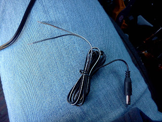
First up, the light wire test which I am actually using to light up my transmission shift handle (clear resin ball). The light bulb comes on and also dims with the dimmer switch. So far so good.
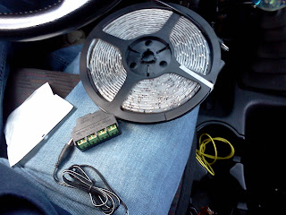
Now to test the rest of the components: junction box and LED spool. Yep, also dim via the dimmer switch!
Now to complete the install.
Install
I decided to solder the line extensions (dimmer and ground) and instead of carefully wearing back the insulation, I simply cut, and stripped the insulation about a 1/2 inch on both ends. Be careful doing this as you only have so much stock wire to work with before you encroach the wiring harness and adapter.After soldering in the power line extension for my junction box (or whatever you plan to use) you see here the wires are exposed. There are multiple ways of keeping this clean and protect the wires. Since the draw I am planning to pull through these wires is low amperage (only pulling for LEDs) I simply used electric tape and sealed up the soldered connections individually. Then sealed up the wire set as a whole with more electric tape.
After soldering the line extensions (power and ground), I tested again. LEDs light up and dim via the dimmer switch!
The rest is up to you how you plan to run your wiring. I went with using a junction box which is going to make the rest of the interior lighting I plan to install simple. No more tapping behind the console as I put the junction box under the steering column behind the lower dash.
Here is the junction box I used. Allows for four connections via the single power source.
And a comparison in size of the junction box next to the LED spool.
Some new lighting all dimming with the stock dimmer switch.


.JPG)
Quite interesting ...i must say..very well written and well described..
ReplyDeleteThanks
How to choose the best Light switches
Cool. Glad it had some use for you.
Delete